[ After finishing the Nixie Clock I started thinking to make something more difficult: an audio amplifier. BUT... I wanted for the first project to avoid the most expensive and difficult to find parts: the transformers, especially the output ones - thus, I needed to think about an Output-TransformerLess amplifier.
By then I was trying to understand this new (to me) 'old' technology; I started studying a lot of documents found on the Internet (see the References). In this search of knowledge, I found this wonderful site: HeadWize, a real mine of ideas, with a pool of competent and helpful enthusiasts.
This is a basically a project found on HeadWize, heavily modified in some parts; in my opinion it is easier to realize than the original (having the components I used by hand).
You could find the original one HERE. ].
Choice of components
[ Well... 'choice' is not the right word here for the main components (the tubes)! I bought on Ebay a set of 8 6DJ8 tubes, and received 8 6Н1П-ЕВ (6N1P-EV).
Looking at the feedbacks of the seller I noticed a lot of negative feedbacks for the same reason, and people that shipped the items back to be refunded did see neither the items nor the refund... so I kept the 6N1P-EVs.
Be extra cautious when buying on Ebay, and always look at the seller feedbacks before bidding!
I discovered later that 6N1P-EV are "better", somehow, than 6DJ8... and tried to make good use of them...
It could be useful to look at the original 6N1P-EV datasheet, that proved to be somewhat hard to find... For actual measurements you can look at this page ]
As a side effect of the 'choice' above mentioned, I needed a high filament current draw than expected (600±35 mA * 3 ≈ 1800 mAmin @ 6.3V), and A LOT of voltage (the original project required 350V, but I simulated a 300V B+ and the results were close enough to perfection to satisfy me; the nominal Ua for 6N1P-EV is 250V). 6N1P-EV is a rugged military-grade tube with very low microphonics (admitted vibration load 6g!) and extended service life (≥ 5000h).
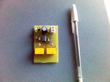
This is the pinout, seen from the bottom:
Due to my prerequisite to avoid any tube-dedicated transformer in the project, and knowing that the current drawn from the high voltage line would be very low (around 30 mA), I thought to (carefully) use an oversized step-down transformer in reverse, coupled to a conventional switching power supply design.
Throughout the project only high quality components must be used; do not be fooled by 'audio' components though... it is enough in my opinion to use precision resistors, low ESR electrolytic capacitors (like the ones used in switching power supplies, for example), and polypropilene for non-polarized ones. Better to be extra cautious in using exactly the same components (model and batch) for both channels.
Where an high precision resistor is needed, you can reliably obtain it from lower precision ones... errors tend to statistically cancel each other, so if you need a 43kΩ,1% you could use:
130kΩ 5% // 330kΩ 5% // 330kΩ 5% // 330kΩ 5% // 240kΩ 5% = 42.99kΩ ≈1%
(And you gain an higher wattage, too. Probably you will need to double check the obtained value with a precision ohmmeter... and change some resistor until the measure is correct).
There is a drawback... if one of those resistors fails, the total value will vary unpredictably. but I cannot see a reason for a quality resistor to fail if correctly dimensioned.
I decided to use low impedance cable, with silicone insulation, to connect the tubes. I don't know if this is really affecting the musical performance, but who knows? This is something you have to decide before wiring everything... and silicon cable does not suffer from heat and age...
Now, let's start from some applied tube theory
In a tube circuit, B+ it is the plate voltage for the operation of the tubes; as in a transistor circuit, it is the voltage applied to the collector, or drain, of the device.The term comes from the times when batteries were used to operate tube type devices, such as radios. The "A" battery was used to power the tube filaments, the "B" battery was for the plate circuit, and the "C" battery was for biasing the tube as a means of controlling it's operation.
First let's choose the B+, trying to keep it low, possibly in the center of the admitted plate voltage of our tube. We choose 300V.
One tube parameter that can be calculated from values on the Ep - Ip (Plate Voltage - Plate Current) curve is known as plate resistance, abbreviated as Rp.
In a properly designed electron tube, there is no physical resistor between cathode and plate; that is, the electrons do not pass through a resistor in arriving at the plate.
You may have wondered, however, why the variable DC voltage source of a tube does not blow a fuse. Doesn’t the plate circuit appear to be a short circuit-a circuit without a load to limit the current? The fact is, there is a very real, effective resistance between cathode and plate.
It is not lumped in a resistor, but the circuit may be analyzed as if it is.
The plate resistance of a given tube, Rp, can be calculated by applying Ohm’s law to the values of Ep and Ip: Rp = Ep / Ip
Amplification is the process of taking a small signal and increasing its amplitude.
But a tube works moving around electrons, and when we make a tube to conduct, we have a measurable current flowing from the plate to the cathode, regulated by the grid(s).
Leaving things like this, instead of amplification, we obtain "conversion", or in other words, we convert a signal voltage to a current variation.
Thanks to Ohm's law, if we want Voltage, and we have Current, we can add Resistance (E = I x R).
In other words, run the plate current variation (caused by the voltage on the grid) through a resistor, and cause a varying voltage drop across the resistor.
VOLTAGE GAIN is calculated by dividing the output signal voltage by the input signal voltage.
Typically for a triode, we want to load it many times its plate resistance.
6N1P has a nominal plate resistance of 4400 Ω so if we load it 5x, this means a plate resistor of 22 kΩ.
Let's look at our typical plate characteristics:
1) Plate Current = 0. This means NO CURRENT at all flowing through the tube.
The only way this is possible is that the Plate Voltage is at B+, because this means there is no voltage drop across the plate resistor, hence zero current.
2) Plate Voltage = 0. This means MAX CURRENT flowing through the tube.
To have max current flowing through, the only way is the plate voltage is at zero volt. It's like saying the tube has shorted itself to ground, so we have a short circuit where between B+ and GND, the only resistor we have is the plate resistor of 22 kΩ.
So we now have 300V = Current * 22 kΩ. Current should therefore be 300 V/22 kΩ = 13.63mA.
(Note that we could proceed iteratively to find the plate resistor value that better fits the plate characteristics of our tube... obeying the tube maximum electrical ratings)
Now mark these 2 points and draw a straight line.
The term quiescent identifies the condition of a circuit with NO INPUT SIGNAL applied.
With a given tube, bias supply, and plate supply, an exact amount of plate current will flow with no signal on the grid. This amount is known as the quiescent value of plate current.
The quiescent value of plate voltage is the voltage between cathode and plate when quiescent current flows.
Now look at the curves again with the drawn load line. It intersects the grid curves from 0V to -8V.
This is important as our signal is going to be positive and negative, so it'll swing up and down this straight line.
If it is quiescent at -6V, it can't swing more than 2V negative though it could swing 6V positive.
So, let's find the middle point of the line and and mark this point on the curve to have the maximum possible swing:
At -8V grid, we are going to get ~13.6mA.
R = VDropAcrossResistor/Current = 8V/13.6mA = 588Ω.
Let's choose the nearest 600Ω for simplicity's sake.
But... why a cathode resistor?
Most amplifier circuits are designed to operate with the grid NEGATIVE relative to the cathode.
The voltage that causes this is called a BIAS VOLTAGE. The symbol for the bias supply is Ecc. One effect of bias (there are several other very important ones) is to reduce or eliminate grid current.
GRID BIAS is a steady, direct voltage that is placed at some point in the external circuit between the grid and the cathode. It may be in the cathode leg or the grid leg. It is always in series with the input signal voltage (voltages in series ADD).
Because the bias voltage is more negative than the signal voltage is positive, the resultant voltage (bias plus signal), Eg, is ALWAYS negative. The signal, in this case, makes the grid voltage go either MORE or LESS NEGATIVE, but cannot drive it positive.
Under these circumstances, the negative grid always repels electrons from the space charge. The grid cannot draw current. Any problems associated with grid current are eliminated, because grid current cannot flow to a negative grid.
The negative bias also reduces plate current flow.
The trick here is for the circuit designer to choose a bias and an input signal that, when added together, do not allow the grid to become positive nor to become negative enough to stop plate current.
In circuits using cathode bias, the cathode is made to go positive relative to the grid. The effect of this is the same as making the grid negative relative to the cathode. Because the biasing resistor is in the cathode leg of the circuit, the method is called CATHODE BIASING.
You will often see a capacitor in parallel with the cathode resistor. Ck serves as an AC BYPASS.
Without Ck, the bias voltage will vary with ac input signals. The capacitor can be said to regulate the current flow through the bias resistor. This action is considered as BYPASSING or eliminating the effect of the AC input signal in the cathode. For all practical purposes, you can assume that AC flows through the capacitor to ground.
But, remember, AC only appears to flow across a capacitor. In reality the AC signal is shunted around the capacitor.
Of course there is A LOT more than this... for the inquisitive minds, here are some references:
A good insight:
Navy Electricity and Electronics training course - Vol 06 Electronic Emission, Tubes, And Power Supplies
(Approved for public release; distribution is unlimited)
A very comprehensive text:
Vacuum Tubes - Spangerberg, 1948
And then there is THE BIBLE:
"Radiotron Designer's Handbook", edited by F. Langford-Smith, Fourth Edition, 1953, 1422 pages.
Be forewarned that if you want to read it you will have to deal with heavy mathematics... but if you succeed in going through it, you will really know everything about tubes.
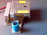
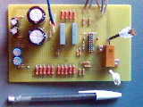
Power supply
The main question here is: how to obtain a 30mA 300V B+ without a tube-dedicated transformer, PLUS a 2A 6.3V heater supply, reducing to a minimum complexity and cost?There are virtually infinite options... and i have chosen this one:
The underlying principle is to make the 555 oscillate, thus generating an alternating current, and feeding with it a transformer wired in reverse; I extracted one from a big wall-wart (primary: 230V 50Hz, secondary: 13.5V 1A), obtaining exactly 300V at U3.
R3 is not there for filtering purposes; it is a bleeder... due to its high value it does not really affect the charging of the capacitor C5, but guarantees that after a reasonable amount of time the capacitor will discharge if the circuit is powered off. I did not like the idea of opening the box after a week for some checks, forgetting to have a 220uF 385V capacitor still fully charged inside!
Be extra careful in choosing the transformer; it must be oversized not to suffer from the stress being used backwards; but do not overkill, we need "only" 30mAmax!
As specified in the original HeadWize project, if you want a dummy load to use when checking the power supply, you will need to cobble together a 13k ohm load capable of dispersing 10 watts.
Notice that U4 is NOT connected to ground... this means that heaters and B+ will not have the same ground plane. But the heaters share the same ground with the 7815...
Everything is powered by a (recovered from trash and repaired!) laptop switching power supply, 20V 3.5A.
To reduce the current requirements and the wiring complexity, I choose to wire the heaters IN SERIES. The same 20V that powers the B+ supply will be wired to the heaters... but with 3 tubes, if we connect the heaters in series, we will achieve 6.6V, not 6.3V. So I connected a 1Ω, 20W resistor in series to the heaters...
B+ switch-on delay
The charging of the 220uF 300+V capacitor is essential to the stabilisation of the B+ supply, but it does not happen instantly!Moreover, the cathodes need to be fully warmed by the heaters before applying B+ to the plates... if B+ is applied to the plates before the cathode is warmed up, internal arcing could occur, damaging or destroying the tubes.
There are different approaches to this problem; being used to programming, I decided to use one of the smallest Microchip PIC processor (12F508A) to implement the following simple logic:
1) Wait for the toggle of a button, with a simple debounce algorithm
2) If the device is currently powered off,
a) Actuate a relay that powers up the heaters; switch on a green led, and pulse a red led
b) Wait 1 minute
c) Actuate a relay that powers up the plates; switch on the red led, and restart from 1
3) If the device is currently powered on,a) Power down the plates; pulse the red led
b) Wait 2 seconds; switch off the red led
c) Power off the heaters; switch off the green led
d) Wait 1 minute, and restart from 1
In the event of a power failure (or if the amplifier is suddenly unplugged) the relays must open, thus allowing a safe restart when plugged in again.
This is the schematic:
The RLY2 will switch on also the B+ power supply... after 60 seconds the B+ capacitor will be charged, and the cathodes will be fully heated.
Here is the (very simple) PIC code, written in CCS C:
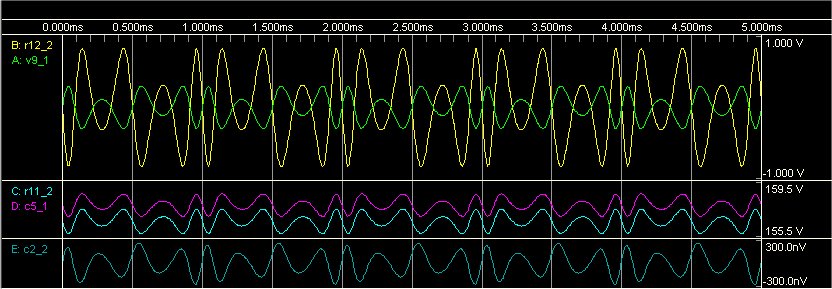
Simulation
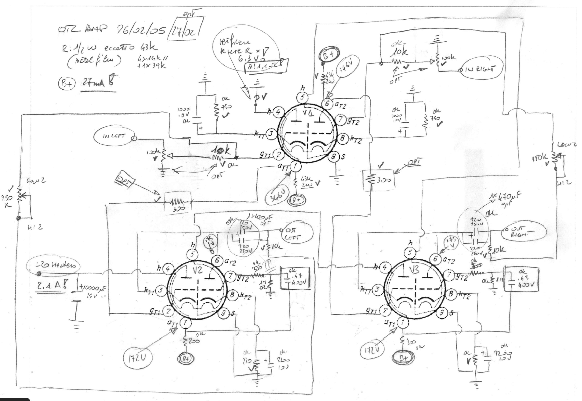
This amplifier has a grounded cathode input stage, and a push-pull White follower output stage, with variable feedback to optimize driving low-impedance headphones.Here only one channel is represented; three tubes will be needed to have two channels (remember that 6N1P is a double triode: V2 and V3 are in a single tube... V1 is half 6N1P!)
Point A is the input signal, varying from -300mV to 300mV, 1Khz
Point B is the output signal; here it is attenuated, but it can swing from -4V to 4V
Point C is the input to the White follower stage from the grounded cathode stage
Point D is the output from the White follower stage
Point E is the followed signal, input to the second triode of the follower stage
RUN!
As you can see everything behaves as expected, looking at voltages in the time domain...
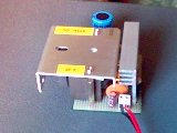
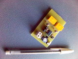
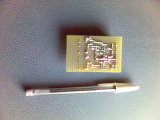
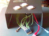
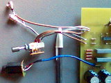
Wiring
Wire everything (excluding tubes, but I am working on it, and soon a double-sided PCB will be engineered), following some simple rules:1) Do not place components too close together, to avoid mutual interferences
2) Place high voltage sections far from low voltage or sensitive ones
3) Phisically separate the power supply from the amplifier
4) Shield anything you can reasonably shield
5) Use shielded, high quality cables for input connections and anything going outside the chassis. (I usually use very good cables from scrap equipment, to save money...)
6) Do not be scared by a tight connector going to the tubes, giving a proper insulation of every connection
7) Think about easy maintenance and repairing; write any useful information (by hand or by any other means) on (or near) the board where components are placed. After a couple of years you will remember little (if anything) of the details of this project... and consider that someone else could have to take care of your work. In any case, write down everything in a lab diary, or on a web page, if you prefer... ;o)
8) ALWAYS CONNECT THE CHASSIS TO GROUND, USE FUSES, AND THINK ABOUT HOW COMPONENTS MAY FAIL IN A DANGEROUS WAY
9) Protect the tubes! (think about your amplifier falling and shattering the tubes, and you or someone else rushing to it and coming in touch to the plates still connected to B+...)
![]()

This work is licensed under a Creative Commons Attribution-Noncommercial-No Derivative Works 3.0 Unported License.